Utility Line Trench Planning and Layout
Last updated: October 24, 2026
Utility line trench planning and layout is the job of turning a blank site into a trench route that can actually be built, inspected, and backfilled without colliding with other utilities, structures, grades, or code requirements. If the line is wrong on paper, the trench will be wrong in the ground, and the fix is usually slower and more expensive than doing the layout carefully the first time. Utility line trench planning and layout is also the subject of this guide, Utility line trench planning and layout — The Complete Guide, and the first job is to make sure the route is practical before anyone digs.
Key Takeaways
- A trench layout is not just a path line; it is a mapped decision about depth, separation, slope, access, and utility conflicts.
- The shortest route is not always the safest route, so the route should be chosen with existing utilities, drainage, and maintenance access in mind.
- Most trench problems come from missing one of three things: utility locate verification, grade control, or a clear plan for crossings and transitions.
- A layout that looks fine from above can still fail if the trench bottom, bedding, or cover depth is wrong.
- This topic is not for guessing in the field. If gas, electric, communications, water, or sewer are involved, the plan should be checked against local code and the utility owner’s requirements.
What a correct trench layout actually needs before a shovel hits the ground

A correct trench layout gives the crew a route, a depth target, a conflict plan, and a clear finish point. It is not enough to draw a line from Point A to Point B; the line has to survive utility locates, slope changes, driveway crossings, easements, and the physical width of the trench itself. For utility line trench planning and layout, that means the first step is always to turn the drawing into a buildable route.
The first thing to define is the utility type. A 2-inch electrical conduit, a 4-inch water service, and a gravity sewer line do not behave the same way in a trench. Depth, cover, bedding, and separation all change. For example, a gravity sewer needs slope control, while a service conduit may need fewer vertical changes but more attention to bends and pull points. Local code and the utility owner’s standard may override a generic plan, so the layout should always be checked against those documents before staking starts. The U.S. 811 system and the utility owner’s own standards are the starting point, not the finish line.
The key here is the trench centerline — notice how it must avoid not only the obvious utility marks, but also structures such as retaining walls, fence posts, tree roots, and hardscape edges. That is what separates a buildable layout from a line that looks fine on a sketch.
| Planning item | What it controls | Common failure if omitted |
|---|---|---|
| Utility type | Depth, bedding, slope, cover | Wrong trench profile |
| Locate marks | Conflict avoidance | Striking an existing line |
| Grade plan | Flow or install elevation | Low spots, sag, poor drainage |
| Crossing plan | How utilities pass each other | Code violations or rework |
| Access plan | Machine approach and spoil placement | Blocked work area |
A layout also needs a clear tolerance. If the trench is for electrical conduit, a few inches off the line may be manageable in open ground, but near a footing, curb, or utility crossing, that same error can turn into a problem. If the line is for sewer, even a small grade mistake can matter because the pipe has to drain under gravity. A generic “close enough” approach is the wrong answer here.
How do I lay out a trench route without hitting existing utilities?
You lay out a trench route by confirming utility locates, marking a workable centerline, checking crossings at the proposed depth, and staking the route so the crew can build it without improvising. That sequence matters because a pretty line that ignores existing services is just a future emergency call.
Start with a current utility locate. In the United States, the 811 call-before-you-dig system is the baseline for underground utility identification, but paint marks are only the beginning. Locates show approximate horizontal position, not a license to dig wherever you want. If the work is near a critical line, ask for owner verification or expose the line by hand before mechanical excavation. The American Public Works Association’s guidance on subsurface utility practices is a useful reference point, and local utility standards may be stricter. OSHA excavation rules also affect how crews handle these conditions.
Use this process in order:
- Confirm the scope of the utility line.
Check: Whether the line is sewer, water, electric, gas, telecom, or drainage, and whether it is a service, feeder, or main.
Do not: Assume one trench section can follow the same rules all the way through. - Request and review utility locates.
Check: Paint marks, flags, tolerance zone, and locate expiration if your jurisdiction uses one.
Do not: Dig from an unverified sketch or old markout. - Walk the route on site.
Check: Drainage flow, driveway crossings, trees, retaining walls, manholes, meter boxes, and other obstacles.
Do not: Plan only from a plan sheet without seeing the ground conditions. - Mark the trench centerline.
Check: Clear, visible paint or stakes at changes in direction and at crossings.
Do not: Mark only the start and end points and leave the rest to guesswork. - Set offset stakes or batter boards if needed.
Check: Fixed references outside the excavation zone so the line can be reestablished after equipment moves.
Do not: Place control points where they will be knocked out by the first machine pass. - Verify the trench width and safe clearance.
Check: Enough room for the pipe, bedding, compaction equipment, and sidewall safety method.
Do not: Plan a trench so narrow that the crew cannot place material correctly. - Document the layout before digging.
Check: Photos, measurements, and notes for depths, crossings, and tie-in points.
Do not: Rely on memory after the first load of spoil has been moved.
A useful field habit is to treat every crossing as a separate decision, but it should be done with professional judgment and the relevant utility owner or qualified designer when conditions are tight or regulated. A gas line crossing 18 inches above a planned water line is not the same as a telecom duct crossing at the same point. The distance, the protection method, and the hand-dig requirement may differ. If the crossing looks too tight, that is the time to redesign, not to “make it fit.” OSHA excavation rules and the local authority having jurisdiction may affect how that crossing must be handled. The APWA and utility-owner guidance are the practical references to check before work proceeds.
Which dimensions matter most in trench planning?
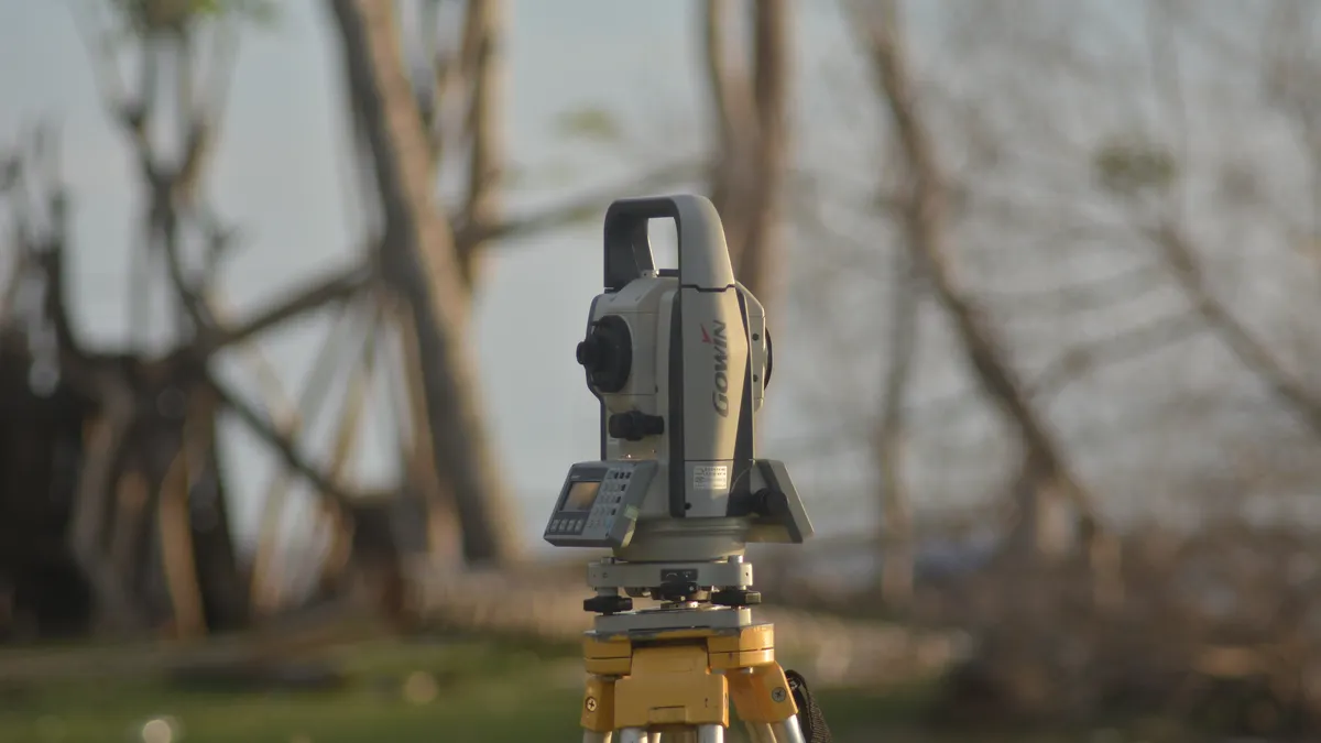
The dimensions that matter most are depth, width, slope, separation, and cover, because those five numbers control whether the line functions and whether it can be inspected, maintained, and protected. A trench that is only a few inches off in the wrong place can fail even if the pipe itself is perfect.
For many utility projects, the exact dimensions come from the utility owner, manufacturer, and local code rather than from a single universal rule. That is why the layout should show target depths and not just a vague “dig here” note. If the line is gravity-fed, slope is critical. If it is a conduit bank, the space around the pipe may matter more than slope. If it passes near another utility, horizontal and vertical separation distances become the main issue.
The table below shows the planning dimensions to think about before excavation starts:
| Dimension | Why it matters | What a good field check looks like |
|---|---|---|
| Depth of cover | Protects the utility from surface loads and frost or damage | Measured from finished grade to the top of the utility |
| Trench width | Allows bedding, placement, and compaction | Enough room for the pipe plus working clearance |
| Slope | Maintains flow in gravity systems | Checked with laser, level, or string line |
| Horizontal separation | Reduces conflict and damage risk between utilities | Measured from utility to utility, not edge of disturbed soil |
| Vertical separation | Protects crossing utilities and supports code compliance | Measured at the crossing point after exposure |
A correct trench bottom is smooth and consistent, not wavy. If the bottom dips and rises by eye, the pipe will follow those errors, and a gravity line can hold water in the low spots. The wrong approach is to excavate first and hope the bedding fixes the grade later. Bedding is there to support the utility, not to erase a bad excavation. For sewer work, a laser level or builder’s level is the better choice than a casual tape-and-eye method.
The same is true for cover. A conduit placed too high can be vulnerable to future digging or surface loading. A line placed too deep may be hard to service and more expensive to install because the excavation gets larger. The best depth is not “as deep as possible”; it is the depth that meets code, protects the utility, and keeps the route practical.
The correct way to set trench grade and slope
The correct way to set trench grade and slope is to establish control points first, then build the trench to those points with repeated checks as excavation moves forward. Slope is not a one-time measurement; it is a condition that has to stay true along the full run.
For gravity utility lines such as sanitary sewer or storm drainage, slope is the heart of the layout. A line with an appealing centerline but inconsistent grade can pool solids or water and cause maintenance problems later. In many residential and light commercial settings, the grade is checked with a laser level, transit, or builder’s level. The exact target slope depends on the pipe size and the design, so the plan needs the actual numbers before anyone starts digging. The American Society of Civil Engineers and local code authorities both treat grade as a critical design and field-control issue.
Use this process when setting grade:
- Identify the required invert elevations.
Check: The upstream and downstream elevations on the plan, including tie-in points.
Do not: Guess the slope from the surface grade. - Set benchmark control points.
Check: Fixed references that will not move during excavation.
Do not: Use loose objects or temporary marks that can be disturbed. - Mark the trench centerline and offsets.
Check: Reusable control outside the cut line.
Do not: Place only one mark at each end and rely on eye judgment in between. - Calculate and mark depth at intervals.
Check: Depth stations at practical spacing, such as every 10 to 20 feet on a straightforward run.
Do not: Stretch a tape once and assume the entire trench matches it. - Excavate in controlled passes.
Check: The bottom stays close to the target grade instead of being overdug.
Do not: Cut too deep and try to recover with loose bedding. - Confirm the trench bottom before pipe placement.
Check: Grade, bedding thickness, and bearing points.
Do not: Lay pipe onto a trench floor that has soft spots or humps. - Recheck after each major bend or tie-in.
Check: Elevation changes at fittings and transitions.
Do not: Assume a fitting will “make up” a bad grade plan.
A straight trench is easier to grade than a trench with multiple turns, but straight is not always possible. When the route bends, the grade control has to continue through the bend, not restart after it. That is where many layouts go wrong: the crew sets grade on the open run, then lets the bend create an unintended belly or rise.
A useful visual check is to picture the trench bottom as a narrow channel with no sudden shelves. The key here is the continuous invert — notice how it should read as one smooth line from one end to the other. That is what separates a line that drains or functions correctly from one that needs a repair call later.
What the layout should show at crossings, bends, and tie-ins
The layout should show crossings, bends, and tie-ins as separate events, each with its own dimensions and notes, because those points are where most field adjustments happen. A trench route that looks simple on paper usually gets complicated at the last 10 feet before a connection or at every place where another utility gets in the way.
Crossings need exact elevation and separation information. If a new line passes under an existing utility, the trench may need to be deeper only at the crossing and then recover its planned grade afterward. If it passes over another utility, the plan may need a protective sleeve, concrete encasement, or a hand-dug exposure zone depending on the utility owner’s rules. That is why a crossing should be marked on the plan with a note, not just crossed out with a pen in the field.
Bends also deserve careful planning. A utility line with too many sharp changes in direction can be difficult to install, pull, or maintain. For conduit, bend radius and pull access matter. For sewer or water, the number of fittings and the risk of settlement at direction changes matter. A 45-degree bend is not just a line change; it changes the excavation footprint and can change how the bedding must be shaped.
Tie-ins should be located where the crew has enough access to work cleanly. A manhole connection, meter tie-in, or existing stub-out is often the point where a good layout proves itself. If the connection point is buried behind a fence, squeezed against a wall, or buried under hardscape, the layout should be revised before digging starts.
The correct layout marks the tie-in with enough information to answer three questions at the site: where is it, how deep is it, and what does it connect to. If those three answers are not obvious, the plan is incomplete.
How should trench planning change for different utility types?
Trench planning should change because each utility has different rules for safety, slope, clearance, and access, and a single trench standard does not fit all of them. A gas line, a sewer line, and a communications duct can share a corridor, but they should not share assumptions.
The table below shows the main planning differences:
| Utility type | Primary concern | Layout emphasis | Common mistake |
|---|---|---|---|
| Sanitary sewer | Gravity flow | Invert elevation, slope, bedding | Ignoring a small low spot |
| Storm drainage | Flow capacity and inlet/outlet alignment | Grade continuity, structure placement | Misaligning the pipe with catch basins |
| Water service | Protection and pressure integrity | Depth of cover, crossings, shutoff access | Placing it where later repairs are inaccessible |
| Electrical conduit | Physical protection and pulling access | Bend count, conduit spacing, warning tape or marker | Too many tight turns |
| Gas | Safety and code compliance | Separation, marking, shallow-risk awareness | Assuming a standard trench is acceptable without owner approval |
| Telecom/fiber | Protection from crush and future disturbance | Conduit route, access points, long-term records | No record of exact path after backfill |
This is where a generic article often gets it wrong: it treats the trench as the same kind of hole for every service. That is a bad habit. A sewer line may tolerate a simple straight route better than a conduit bank, while electrical duct may require pull boxes or handholes that change the layout entirely. A water service may need a route that stays away from roots and allows future valve access. Gas work often has stricter owner and code controls that should be checked before anything is staked.
The practical rule is simple: the utility type decides the layout, not the other way around. If the site forces a bad layout, the answer is redesign, not forced installation.
What should the field crew verify before backfill?
The field crew should verify alignment, grade, bedding, crossings, and photos before backfill because once the trench is closed, mistakes become expensive to find. Backfill is the point of no easy return, so the checklist has to be done while the line is still visible.
Use this pre-backfill check:
- Confirm the utility is in the correct location.
Check: Centerline, offsets, and relation to stakes or reference points.
Do not: Close the trench before confirming the line has not drifted off layout. - Verify depth and cover.
Check: Measured depth at several points, especially at crossings and grade changes.
Do not: Take one measurement and assume the rest match. - Inspect bedding and haunch support.
Check: Pipe or conduit supported uniformly, with no hard voids or rock contact.
Do not: Backfill around a utility that is bridging over a pocket. - Check slope or levelness.
Check: Continuous grade for gravity systems, level set where required for conduit or structures.
Do not: Let the line ride over a hump near a joint or fitting. - Review crossings and protection.
Check: Sleeves, separation, warning tape, marker wire, or protective measures specified on the plan.
Do not: Assume the crossing is “fine” because it looks clear. - Take documentation photos.
Check: Wide shots and close shots with tape, level, or stake references visible.
Do not: Backfill without a record of what was actually installed.
A good photo set is not a vanity album. It should show the route, the depth reference, the crossing detail, and the final tie-in point. If the job ever needs troubleshooting, those images can save hours. A bad habit is to photograph only the finished surface. That tells future crews almost nothing about what is below grade. The USGS and utility-owner records practices both support keeping usable documentation, not just surface images.
The most honest limitation of trench planning is that it cannot solve every field surprise. Hidden rock, undocumented utility stubs, wet soil, or a surprise obstruction can force a change. That is why a good plan includes room to adjust without losing the line’s basic geometry. The best layout is precise, but it is not brittle.
When is a trench plan not enough on its own?
A trench plan is not enough on its own when the site conditions are uncertain, the utility type is sensitive, or the route crosses multiple existing services in a tight corridor. In those cases, the plan needs field verification, utility owner input, and sometimes subsurface investigation before the trench route is finalized.
This is the point where a reader should be clear about who this guide is not for: it is not a substitute for licensed design, utility-owner approval, or site-specific engineering on regulated work. If the project involves a public main, a gas installation, a complex sewer grade, or a corridor packed with existing utilities, a generic layout is too blunt an instrument. Local code, the authority having jurisdiction, and the utility owner can require separations, inspections, or protective methods that change the trench completely. ASTM and utility-owner specifications are the kind of documents that can change the field requirements.
A site with no reliable records may need potholing, vacuum excavation, or other verification methods before the main trench is staked. That adds cost and time, but it is usually cheaper than repairing a severed line or redesigning after excavation has started. In one documented utility practice example, vacuum excavation is used specifically because it reduces the risk of damaging buried lines while confirming what is actually underground.
The best planning mindset is simple: the drawing tells the crew where the trench is supposed to go, and the field tells the crew whether it can actually go there. When those two disagree, the field evidence wins, but the redesign should still preserve the utility’s function, the required separations, and the final access needs. That is the difference between a layout that merely exists and one that gets built cleanly.
Drafted with AI; not yet reviewed by a person.