How to Plan a Multi-Utility Trench Layout
Last updated: October 21, 2026
Quick Answer: A multi-utility trench layout is easiest to plan when you map the route, branch points, and future reserves on paper before digging; in practice, a 1-inch-to-10-foot sketch is a workable early scale for How to Plan a Multi-Utility Trench Layout. A multi-utility trench layout is the map that tells a property owner where electric service, gas service, water service, sewer service, and telecom service should run, where they should branch, and what gets reserved for later. The right plan, with a professional review if needed, can prevent dead ends, reduce rework, and keep one excavation from turning into three.
Key takeaways
- Start with the services you need now, then mark the ones you may add later.
- Put the trench plan on paper before anyone digs, with branch points and tie-in locations shown clearly.
- Decide which service gets priority in the route, not just which one is cheapest to install.
- Keep shared runs simple; every extra bend, split, or crossing makes coordination harder.
- Leave space for future utility upgrades, even if the conduit or pipe is not installed on day one.
- A good layout is a coordination tool, not just a sketch for the excavator.
What a multi-utility trench layout actually solves
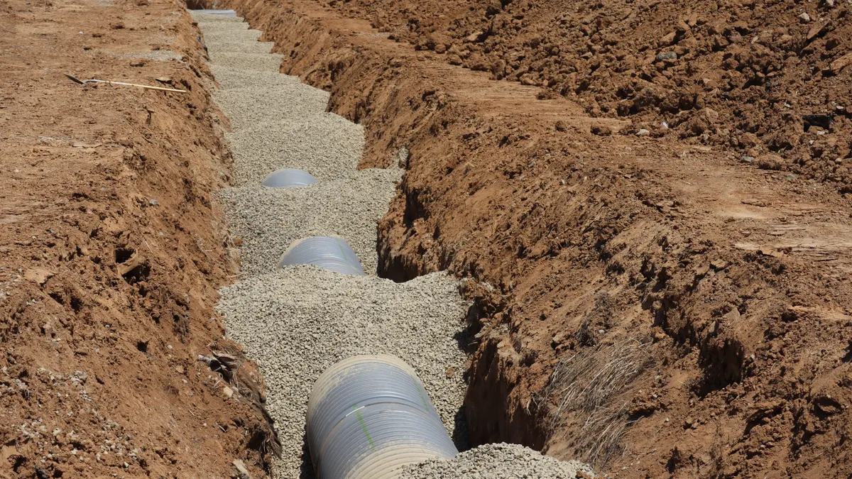
A multi-utility trench layout solves one problem: how to fit several utility runs on one property without forcing last-minute changes in the field. It turns a loose list of services into a routed plan with start points, branch points, and endpoints. That matters because electric service, gas service, water service, sewer service, and telecom service do not behave the same way, and they rarely line up naturally.
The layout should answer three questions before excavation starts: where does each utility enter the property, where does it travel in the shared trench, and where does it separate from the others? A layout that misses any one of those usually creates conflict at the trench bottom or at the building entry. A common example is a utility run that looks fine on a site sketch but fails when one branch needs to turn toward the house and another needs to continue to a detached garage.
This is also where a property owner needs to think beyond the first installation. A driveway, future shop, pool, or accessory dwelling unit can change the route later. Planning for a 2-inch spare conduit or a blank sleeve for future telecom is often cheaper than reopening hardscape later. With a professional review, a site-specific route can account for those changes before excavation starts. That said, a multi-utility trench is not always the right answer, and a site with crowded access, a steep grade, or a known need for frequent maintenance on one service may work better with separate trenches.
A useful layout is specific enough that a utility coordinator, designer, or excavator can follow it without guessing. If the plan only says “run utilities to the house,” it is not a layout yet.
How do you plan a multi-utility trench layout?
You plan it by fixing the service list, tracing a route, assigning branch points, and then checking that every utility has a clear destination and a realistic install order. The simplest way to do that is on a scaled site plan, even if the plan is only a 1-inch-to-10-foot sketch for an early concept meeting.
-
List every utility you need now and later. Write down electric service, gas service, water service, sewer service, and telecom service, then mark which ones are immediate and which are future additions. The result is a scope list that keeps the trench from being sized around guesswork.
-
Mark the building entry points on the site plan. Place the meter location, panel location, sewer tie-in, water entry, and any telecom demarcation point on the plan before you draw the trench line. That gives the route real targets instead of a vague path to “the house.”
-
Choose the main corridor first. Draw the longest shared run from the property edge to the main structure, then keep it as straight as the site allows. A short, direct corridor usually reduces conflict and leaves more room for branch points near the structure.
-
Add branch points where one utility leaves the shared run. Mark each split clearly, such as the point where gas peels off toward an exterior wall or where telecom branches toward a detached garage. A branch point should be obvious on the drawing, not hidden inside a note.
-
Sequence the utilities in the order they will be coordinated. The order matters because some lines need more planning around tie-ins, access, or later inspection steps. A layout that shows the sequence saves time when contractors coordinate the trench and avoids having one trade block another.
-
Reserve future space. Leave a blank path for an extra conduit, an oversized sleeve, or a second route to a future outbuilding. Even a simple note like “future telecom” or “reserve for irrigation control” can prevent the trench from being packed so tightly that nothing else fits later.
-
Review the plan against the property’s fixed constraints. Driveways, retaining walls, trees, steps, septic components, and easements can all force rerouting. If one of those sits in the way, redraw the route before it becomes a change order.
What should go in the shared trench, and what should stay separate?
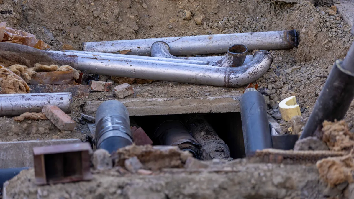
The shared trench should hold the services that can be coordinated as a single route, while separate trenches make sense for runs that need isolation, easier maintenance, or different future access. That is the practical dividing line, not a rule of thumb with one universal answer.
A shared trench works best when the route is short, the property is compact, and the utilities can enter the property in roughly the same direction. A typical residential layout might share the long approach from the property line to the house, then branch near the building. That keeps excavation simple and reduces the number of disturbed areas. It also makes staging easier when one crew is handling multiple services across a narrow corridor.
Separate trenches can make sense when one utility needs more frequent service access, when a future expansion is likely to branch far from the others, or when the site makes a clean shared path awkward. A telecom duct to a detached office, for example, may be easier to isolate from the main utility corridor so a later upgrade does not disturb water or sewer work.
The trade-off is real: one trench is usually easier to coordinate, but it can become crowded if the layout is vague. Separate trenches reduce congestion, but they increase excavation, restoration, and the chance of duplicated effort. On a small lot, that extra excavation may not be worth it. On a larger property with multiple structures, separate paths can be the safer long-term choice.
The right answer depends on how many services are entering, how far they must travel, and what the property owner may add later. A multi-utility trench layout is wrong for a site if it forces every service into the same exact path when one or two of them clearly belong elsewhere.
How do you plan the service order without boxing yourself in?
You plan the service order by putting the most route-sensitive and coordination-heavy lines on the paper first, then fitting the easier runs around them. The point is not to make one utility “first” in every case; it is to avoid a layout where one line blocks another at the exact point where the trench turns or branches.
A practical order for planning looks like this:
- Start with sewer service and water service. These usually set the main approach because they have fixed entry points and limited flexibility once the building tie-in is chosen. If the house location is already set, these two often anchor the corridor.
- Add electric service next. Electric service often needs its own dedicated path within the overall route, so it should be placed where it can enter cleanly without crowding the other lines.
- Fit gas service with clear branch logic. Gas service should be shown as a deliberate path, not as an afterthought squeezed into a leftover space on the sketch.
- Place telecom service with future flexibility in mind. Telecom service is often the easiest to adapt later, which makes it a good candidate for spare conduit or a reserved branch point.
The result should be a sequence that can actually be installed and inspected in stages, without forcing one contractor to wait on another because the planned route made access impossible. A good plan also avoids putting every service in the same exact line from start to finish. Even in a shared trench, the drawing should show where each utility peels off or changes direction.
One mistake here is treating the service order as a purely aesthetic decision. It is not. The order affects coordination, access, and the amount of rework needed if the building plan changes later. A layout that ignores sequence can still look neat on paper and fail in the field. For a site-specific sequence, a utility designer or coordinator can help match the drawing to the installation order.
For broader context on trenching methods and when each approach fits, the hub on utility line installation methods and use cases is the right place to start. For general trench safety and planning guidance, OSHA’s excavation resources are also a useful reference.
What should the layout show so crews do not guess?
The layout should show the route, the branch points, the utility list, and the future reserve areas with enough clarity that no one has to improvise in the trench. If a drawing needs a verbal explanation to make sense, it is too thin.
At minimum, I would expect these elements on the plan:
- Property boundaries and the building footprint
- The planned entry point for each service
- The shared trench corridor
- Every branch point, marked plainly
- Any future utility reserve or blank conduit space
- Fixed obstacles such as driveways, walls, trees, and septic components
- Notes for coordination with the utility provider or installer
A useful layout also distinguishes between what exists now and what is only planned. A line type, label, or note can do that. For example, “install now” and “future spare” should not look identical. That distinction matters when a property owner revisits the plan six months later and cannot remember which line was meant for a future garage.
This is where many generic sketches fail. They show the trench as a single line and the utilities as labels, but they leave out the exact places where a branch starts or where a future line can come out without reopening the entire corridor. That omission costs time later because a crew has to stop and ask what the sketch meant.
A good layout also includes a simple legend. It does not need to be fancy, but it should be consistent. If the plan uses one symbol for a sleeve, one for a branch, and one for a future expansion, those symbols should be the same everywhere on the page. A layout with three different meanings for the same line style is not a plan; it is a puzzle.
Which mistakes cause the most rework?
The biggest mistakes are cramming too many services into one unstructured run, ignoring future expansion, and leaving branch points vague. Those errors usually cost time first, then money, then flexibility.
A crowded shared trench without clear branch points is the classic failure. The cost is not just a messy installation; it is the chance that one utility has to be rerouted after the trench is already open. The fix is to draw each split and endpoint before excavation begins.
Another common error is planning only for the present build. If the property owner may add a detached garage, studio, or extra telecom drop later, the layout should reserve a path now. Skipping that step often means cutting pavement or re-digging landscaped areas later.
A third mistake is assuming one utility provider will adapt to the others’ needs. That is risky. Utility coordination works best when the property owner or designer has already shown the intended path and branch points, then asked the providers to review the plan. If field crews are left to sort out the whole layout on site, delays are more likely.
The last mistake is treating the trench as if it were only a straight line. Real properties have slopes, corners, and obstacles. A 12-foot retaining wall or a tight side yard can change the best route completely. If the plan does not acknowledge those constraints, it is missing the part that matters. A designer or excavator should verify the route against the site before digging.
How do you plan for future utility upgrades?
You plan for future utility upgrades by reserving path space, marking likely branch points, and keeping the main corridor easy to reopen if needed. That is the difference between a plan that works for one project and a plan that still works when the property changes.
The easiest future-proofing move is to include a spare conduit or sleeve where later telecom or control wiring may be needed. Another is to leave a clean branch point near the building or outbuilding so a later line can leave the shared corridor without crossing another service. If the layout is cramped today, it will be expensive later.
Future planning also means thinking in terms of access, not just installation. A line that is technically possible to add later but would require cutting a finished driveway is a weak plan. The better route is the one that leaves a reachable corridor or at least a documented path that a future contractor can follow without guesswork.
This does not mean every trench should be oversized “just in case.” Oversizing everything can waste space and complicate coordination. The right move is targeted reservation: one or two obvious future paths, not a blank trench with no structure. A property owner who knows the near-term plan for the site can usually make that call more accurately than someone who tries to build for every possible future.
A multi-utility trench layout works best when it is honest about trade-offs. Some sites are ideal for a shared run. Others need a split layout. The point is to decide that on paper, before any service is pulled into place and before the first shovel changes the ground.
Should utilities go in one trench or separate trenches?
One trench is usually the better starting point when the services share a common route and the site is tight. Separate trenches make more sense when one utility needs easier access, a different future path, or less interference with the others. The decision should follow the site, not a habit. A 20-foot branch to a detached building may justify its own route.
What should be installed first in a shared trench?
The layout should place the most route-defining services first, then fit the others around them. In practice, that usually means water service and sewer service anchor the plan, with electric service, gas service, and telecom service coordinated around those entry points. The exact sequence depends on the property and the installers involved, but the drawing should make the order obvious.
How do you plan for future utility upgrades?
You plan for future utility upgrades by reserving at least one clear path for later service, marking branch points that can be used again, and avoiding a layout that leaves no room to expand. A spare conduit, sleeve, or documented corridor can save major excavation later. The best future plan is specific, not vague, and it should match the property’s likely next phase.
Drafted with AI; not yet reviewed by a person.